Number 1 Mark II Lightweight 10-cwt Airborne Trailer

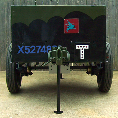
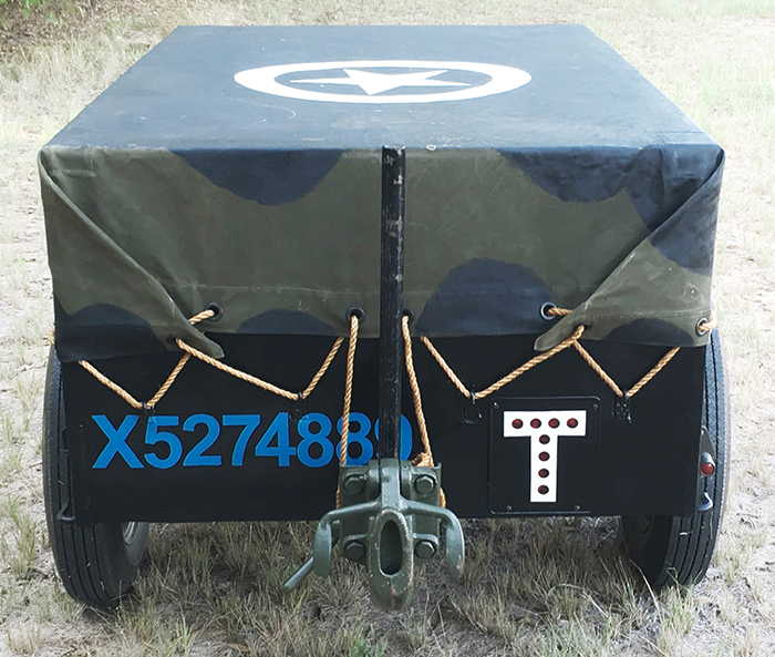
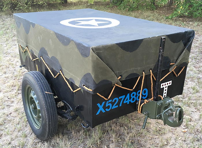
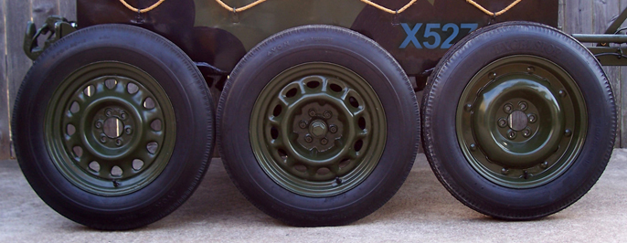
Census numbers for all trailers have an X prefix. Army Council Instruction 1672 of 1943 stated that all W.D. vehicles will display their vehicle number on the offside and on the rear. This was further amended by Army Council Instruction 570 of 1944 which defined the size of figures at 3.5 inches high, 2.5 inches wide and 5/8 inches thick. They should be painted white with the exception of vehicles used by the airborne forces which should be painted blue. A.C.I 570 also reiterated that the vehicle classification letter (again this is X for trailers) must be included as the W.D. number would be incomplete without it. As a result of this, some earlier war photographs of trailers will show the "X" above the number since it was added after-the-fact.
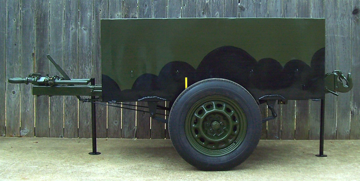
Vehicles used by the airborne forces will have a yellow 5/8 inch wide stripe painted on the nearside which serves to identify the center of gravity needed for proper loading into a glider or powered aircraft. For the cargo trailers, this was located seven inches in front of the axle. Early war the stripe is usually found at the top of the sidewall but as this is obscured by the tarp that was issued with the trailer, the location moved to the bottom of the sidewall.
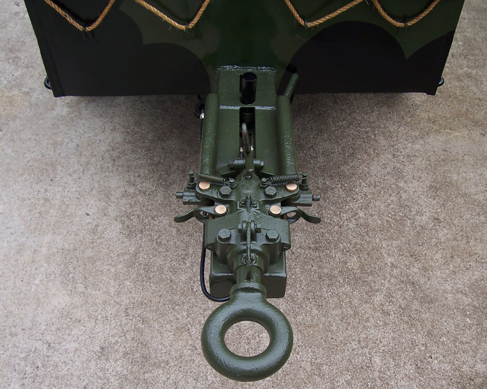
Likewise the Lunette shown on this trailer is the larger late war pattern when compared with the lightweight style typically seen on airborne trailers. This larger size Lunette is compatible with the larger size British pintle hooks found on Universal Carriers and trucks.
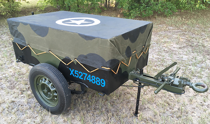
Each trailer was supplied with a waterproof canvas tarp. These were usually painted with a disruptive pattern in compliance with Army regulations with procedures laid out in Military Training Pamphlet Number 46 in seven parts, specifically Parts 1, 4 and 4A. Basically the top would be painted black and it needed to overlap onto the sides enough to break up the straight edges. And any disruptive pattern on the vehicle needed to be continued onto the tarp to likewise eliminate it forming a clean straight edge where it covered the vehicle.

White five-pointed recognitions stars were painted onto Allied vehicles to help prevent friendly fire incidents. Size and placement varied depending on the vehicle, theatre and unit. With the advent of the June 6, 1944 Normandy landings and widespread adoption of aircraft fired air-to-ground rockets, a white circle was added surrounding the star. These will be seen with broken circles indicating they were painted using a stencil, or with solid rings indicating they were painted without a stencil. The generally held belief for adding either pattern circle is that the star on its own can resemble a Swastika at aircraft standoff distances greater than 3500 feet.
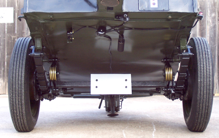
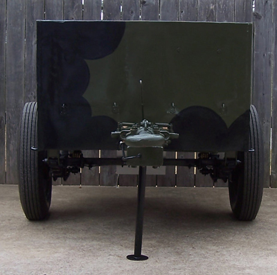
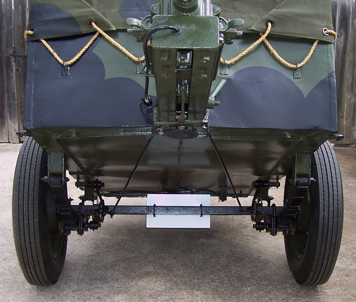
The white metal square on the axle is used with a flood lamp for blackout convoy purposes in the same way as the Airborne Jeeps rear differential was painted white. The flood lamp and right side rear running light are turned on by the black bakelite switch beneath the trailer. A second connector is also on the rear to allow power to be supplied to another trailer if needed. Power is passed from the towing vehicle down the cable in the center which runs to a Bakelite junction block. It then goes to the Bakelite lamp switch which has two positions. One to supply power to the blackout axle flood lamp and one to provide power to the running lamps at the sides. In this case, only one running lamp is installed but a second could be fitted to the bracket on the opposite rear corner.
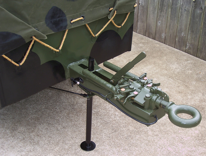
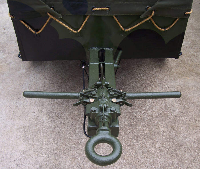
The power cable that runs to the towing vehicle could be plugged into a receptacle on the side of the front tow beam when not being used. This secured it until needed and protected it from becoming damaged. The handle seen in the center above the tow beam is the hand brake lever.
The trailer had hand-operated wheel brakes which were used when the trailer was unlimbered and parked. When the handle is pulled towards the body of the trailer, it levers a pair of rods forward and activates the brakes.
Tools that were issued with the trailers included a puncture repair kit (yellow tin made by Dunlop in this case), a Tubular Socket Wrench in 3/8 British Standard Whitworth along with a Tommy Bar for removing the rim nuts (white metal pair of tools), a Tyre Inflater with Valve Stem Hose, and a Grease Gun (Tecalemit brass hand pressed type).
As this trailer is being used to support a towed 4.2-Inch mortar, the shot above shows the typical load. Each of the mortar bomb carriers holds a pair of 4.2-inch bombs which each has a weight of thirty pounds. Five carriers lay on their sides on the floor. And twelve more carriers sit upright on top of them just beneath the troop bench. A single strap runs lengthwise though all of the mortar carrier handles and the trailer cargo straps pass through this to help secure the entire load which has a weight of 1020 pounds. The open space seen on the floor would be used for camouflage nets used with the mortar, along with pioneer tools and other required equipment. Mortarmen can sit comfortably on the bench with their feet on the floor across from the mortar carriers. Examples of the 4.2-inch H.E. and Smoke bombs are shown laying on the bench.
Jeep, trailer with ammunition and 4.2-Inch mortar with towed base plate in caravan.